Friday 1 May 2020

Arc Command on SNS-3V DRO

A while back I purchased an unbranded 3-axis DRO from Aliexpress and mounted it on my Optimum BF-20L benchtop mill. I've been pretty happy with the performance and it makes the mill a lot more fun to use.

Today I had the need to put a radius on a piece of work in the XZ plane and could not figure out how to do it. The manual was little help as not only was it translated from Chinese, it was clearly for a different model of DRO. Mine doesn't have the option of "simple" or "smooth", for example. A member of a Facebook machining group came to my rescue. For the purposes of posterity (ie I'm going to need to look it up next time I use this function) I decided to document this.

Some important points:

  • 0 degrees is at 3 o'clock, 90 degrees at noon, and so on.
  • Once you enter arc mode, it assumes your current location to be X0Y0Z0, ignoring what the coordinates are set to. This means it's important to put the mill table at the centre of the radius of the arc before you enter arc mode.
  • If you're using a standard end mill, use the corner of the end mill as X0Z0, and use 0 as the cutter diameter. I assume, but have not verified, that if you're using a ball-end mill the centre of the tool would be X0Z0 and you would enter twice the radius of the tool as the tool diameter.
  • It's important that the X axis increments in the right direction - as you move the table left, X should increment in the positive direction. I had to go into the setup (hold down the decimal point key as the DRO boots up) and change the 0 to 1 in the X setup.
So let's get started. First touch off the top and right sides of the job and zero the DRO. I zeroed the Y axis at a position just in front of, but clear of, the job:


Then navigate to X and Z coordinates that match the radius of the arc you're cutting. I wanted a 5mm radius, so we go to X -5 and Z -5.


Then enter the Arc mode - it's the one below the 0 on the keypad. Set this to XZ using the arrow keys. Use the ENT key to scroll through the settings.


Set X0 Z0 as your centre.


Enter your radius, in this example, 5mm.


Set tool diameter to zero.


Set max cut to 0.5mm. I tried 0.25mm but that doubles the number of passes and I don't think it decreases the amount of time it takes to file it smooth afterwards.


Set start angle to 90 degrees. This starts the process at 12 o'clock.


And set end angle to 0 degrees (3 o'clock). If you reversed these two numbers, it would work anti-clockwise rather than clockwise.


We want an outside corner, so set it to RAD+TL.


The next press of the ENT key starts the sequence. You can ignore step 1 as it's basically a start position and doesn't actually cut. Advance through the sequence using the arrow keys and navigate to position 2. I strongly suggest you lock your travels between moves, certainly at least your Z. I was able to get away with slightly tightening my X and leaving it there. Be aware if you have backlash in your X leadscrew, if you're adjusting "uphill", vibration will make the handle fall through the backlash, potentially moving the X table during the cut. The last step of the sequence involves a very small X movement (sometimes less than 0.1mm on smaller rads) and can probably be ignored.


The result of 16 passes (about six minutes) after a quick brush with a wire brush to knock off the burrs:


You may notice the shiny packing tape over the display. This is holding some pieces of translucent green plastic over the LED display. I found that there was not enough contrast on the display and it was washing out under my shop lights, making it very difficult to read without squinting. I'll come up with a better way to hold these on. Here's a shot of it without the plastic:


Hopefully this has helped somebody - let me know in the comments below. I also could have used a rotary table, disc sander, or simply a file to achieve the same result, but someday I may want to put an arc on longer sections so I wanted to nut this out.

Cheers!
TSIII


Saturday 10 January 2015

Building the Primo

The Primo is an educational toy designed to teach programming concepts to children without the need for them to be literate.  The Primo was "Kickstarted" and commercial product is being delivered early 2015.  In addition to selling it as a product, the designers have open-sourced the design and have even put together a how-to guide.  See primo.io

I thought this would be a neat project, combining woodworking and electronics.  I am fairly well-versed in the former but only have a shallow knowledge of the latter, so I saw this as an opportunity to learn lots about electronics.  The Primo uses two Arduino, wireless communication, and gearmotors.

I:  The wood parts.
The instructions call for Primo to be made from 1mm and 4mm plywood.  I have used birch ply in the past to build projects and loved its dimensional stability and resistance to warping.  I had hopes of using it on this project but could find none affordably here in New Zealand.  I settled on 4mm Fijian Kauri ply purchased from a local builder's yard.  A full sheet was about $NZ50.  I could find no 1mm ply, so on the suggestion of the designers I used 1mm card stock purchased at a local stationery store.  This is basically used as a shim layer so the overall strength isn't greatly important.  I had the parts cut out at our local fablab (Fab Lab xChc).  The fablab had just opened and were still coming to terms with the operation of their 150W ThunderLaser so the cutting was not ideal, but successful (and cheap!).  We had issues with the ply not sitting flat on the bed, so the areas that warped upwards were outside of the focus of the laser.  Also had significant charring, and the kerf ended up being about .43mm (0.017") which to me is quite wide.  Because the layout of the parts is "nested", the edge of one part ends up being the edge of another, so we couldn't tweak the laser to cut farther from the centreline.  This isn't a huge problem, but on corners of the control box and of the Cubetto remote, the meshing sides don't sit entirely flush with each other.  More of an aesthetic issue in that case, but the charring has required significant hand sanding as well.

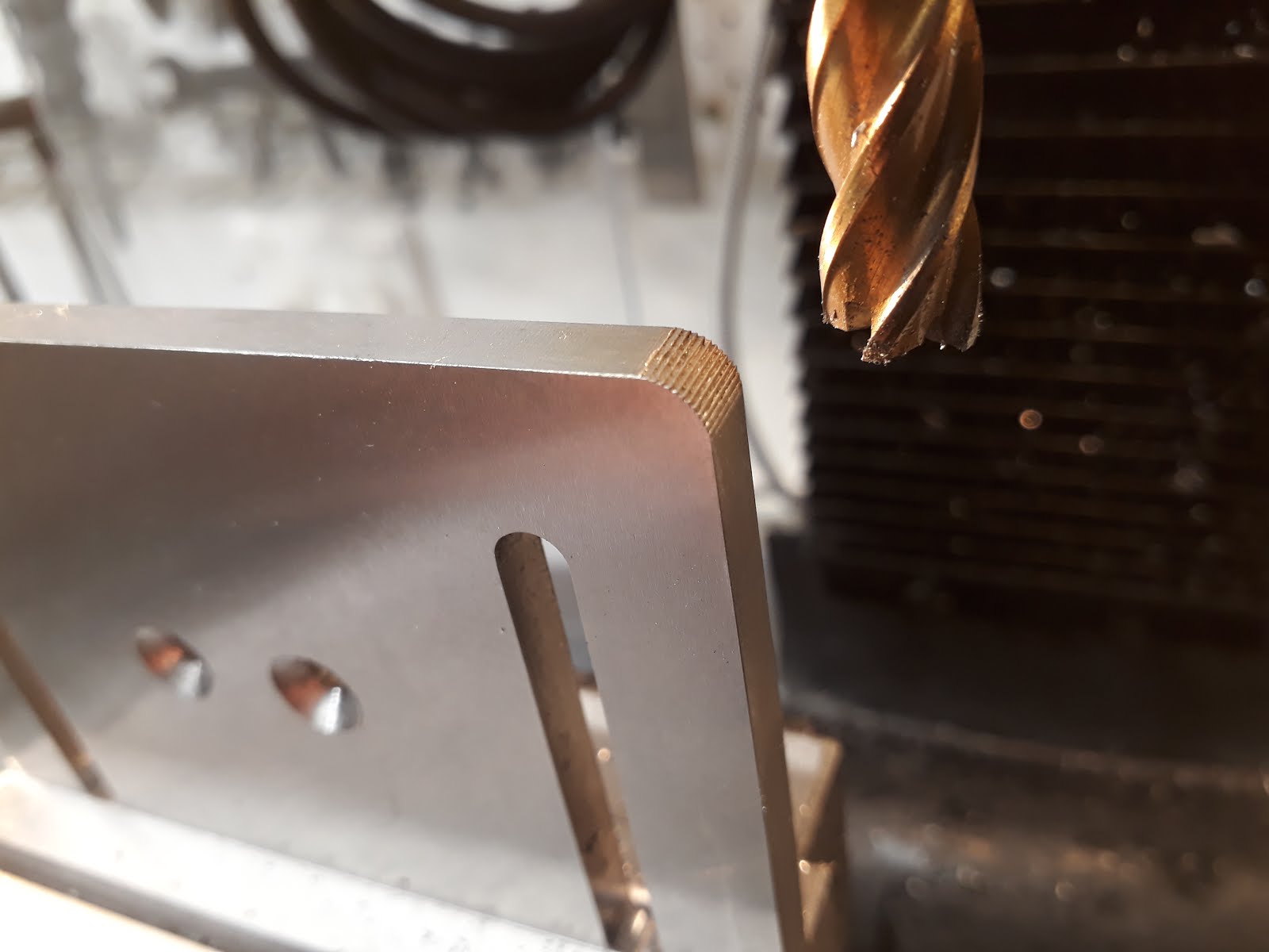
Laser cutting the 4mm ply in progress


Cutting the 1mm card stock.  We had to put slots and profile in different layers so all the slots were cut first.  As soon as profile was cut, the air blow on the nozzle would occasionally blow the piece clear and if the slots hadn't been cut yet, the part would be a loss.

Selected parts after laser cutting.


Control Box:

The first step is to glue control box parts 1+2 and 3+4 together.  To keep them aligned as I glued them, I drilled the screw holes in upper right and lower left corners out to accept a couple of drill bits (I used a #29 and #30).  We were out of waxed paper so I laid plastic cling wrap on the workbench and also between the two sets to keep squeezeout from sticking.  I used aliphatic resin woodworking glue.  I had issues with the warped layers not pulling together well enough.  Ideally a vacuum clamping setup or luthier's go-bar deck could be used for this, but I had neither so used luthier's cam clamps and Vise-Grip quick clamps on two edges, and then piled bricks on top.  After an hour or so, I unclamped everything, cleaned up excess glue, then re-clamped.

Aliphatic resin glue (Tite-bond to most US woodworkers) applied to top of part 2
The stack of top parts being glued. Note drill bits in corners for alignment. From the workbench upwards, the layers are
-clingwrap
-part 4 / glue / part 3
-clingwrap
-part 2 / glue / part 1
-bricks


Instruction blocks

I glued the paper layer to wooden layer with four small dots of CA glue.  Because the laser cut more off the edge of the wood than it did off the paper, the paper piece ended up being slightly larger.  I aligned the curved bit and trimmed excess off flat edge with sharp chisel.  If you try to sand it, the paper edge will "fluff" up.  Use a vise - that scar on my index finger is from the last time I tried to hand-hold something while using a chisel.


Copper tape.  Instructions call for 5mm, I had 6mm.  I found I needed to cut it to 4.5mm to thread it through the slots in the instruction blocks.  Also, instructions call for 40mm lengths, I found 30mm lengths were better.  Taping it to cutting mat made narrowing it easier, and then it was easy to count three squares to cut it to length.

Magnets purchased from Aliexpress.  4mm dia x 3mm thick.


After dropping magnets in the holes in instruction blocks, I placed them on a metal rule to ensure magnets were fully seated, then applied a small drop of CA glue.  It is essential that you retain the same magnet polarity for each instruction block.


I bent the legs of the resistor with tweezers so it would sit flush.

Resistor soldered to instruction block base.  I trimmed the ends with a very small pair of side cutters.  If you don't have a pair of these, you may wish to trim the resistors before soldering.  Another option would be to drill a tiny hole through the copper and bend the legs to drop in there, but I don't currently have a drill press, and didn't fancy trying my luck with a hand drill.  On the right, I'm making sure the intermediate layer clears all the solder, on a couple I had to file off excess solder for it to fit.  Check them as you go.

Scratchy break!


Back to the Control Box

Next, the magnets were dropped in the holes on the wood side (double check polarity! Last chance...) and secured with CA glue.  Then strips of tape were cut for the contacts.  Fortunately the slots in the top were wide enough that I did not need to trim the tape to width as I did on the blocks. I found it helpful to line both sides with a pencil to help lay the tape down straight.  Test fit the LEDs to the top board (I had to open up the holes with 5mm drill bit).  Then I glued the 1+2 and 3+4 pieces to each other.

Gluing sides to back.  I had to screw back to workbench as it was quite warped.  I used CA glue with accelerator.  And a glass of whiskey. Arduino Mega will go in upper left corner.
Top on, looking good.  Top has about five coats of Danish Oil.
Back with rubber feet.  The outline in lower left was supposed to be burned into the top of the back as registration for lining up something.  Not sure what it was supposed to be for.  It accidentally got put on the cut layer during laser cutting.


Beginning to wire up underside of top.


 Ribbon cable used to wire LEDs.

Soldering ribbon cable was a bit fussy but not as bad as I expected.  These plug in ports 30-45 of the Arduino.


Second ribbon cable soldered, this one to two 8-pin single row headers.  These go to Anaolg 0-15 inputs of the Arduino.  You can see the Mega mounted in the bottom of the case.  Still waiting for the wireless card to arrive.
Mostly completed main unit.  Instead of trying to paint the outline around the subroutine steps at the bottom, I had our local Fablab take the rectangle shape out of the laser cutting file and cut it out of green vinyl.  far easier than trying to mask and paint.  Now to start on the Cubetto!


Cubetto:

This is where it starts to get a bit curly as there simply isn't enough information in the instructions to build this.  I've spent quite a bit of time going over data sheets for the optosensors and the motor driver to try to trace what goes to what.  In addition, the instructions don't tell you what Arduino pins you need to hook to, I had to reverse engineer that from the software.

The "Elecrow" protoboard I bought off Aliexpress.  The instructions specify one from the official Arduino store but it was out of stock for months.  Here I've wired up all the outputs from the motor driver chip.  The analog inputs from the wheel optosensors attach to A1 and A4 under the board as I ran out of room on the top.  The pins at the top and bottom of the prototyping area go to the motors and optosensors.  Motor driver chip and Xbee unit on foam at left.


My notes.  Be aware that my understanding of a lot of this is fairly vague; I'm learning a lot as I go!


This document will be updated as I construct the Primo.  Please contact me with questions or if you wish to share your experiences - Thaddeus Swarfburn


Parts sources:

For economic reasons ;) I've used some different sources for my parts than those suggested by the designers.  The following is a table of where I sourced my parts:

4mm Wood:  Fijian Kauri ply, local builder's yard (ITM) about $50 (full sheet)
Copper tape:  Had on hand from aborted slot-car track building project.  VentureTape MasterFoil Plus.  Try stained-glass supply houses or workshops.
Paint: I'm using mostly "test pots" of Resene (NZ brand), about $5 each.
  • Green - Kermit
  • Yellow - Turbo
  • Blue - Resolution
  • Red - Red Enz brand fire engine red
Cubetto:

Arduino UNO copy: US$3.56 - Aliexpress
Elecrow Proto Wireless Shield - US$9.00 - Aliexpress
XBee Series 1: NZ$34 - robotbits.co.nz
SolarBotics Wheels x 2 : NZ$5.75 ea - robokits.co.nz
SolarBotics Gear Motors GM3 x 2 : NZ$9.99 ea - robokits.co.nz
2 Ball Casters : NZ$2.86ea - robokits.co.nz
SN754410 Motor Driver : US$5.99/5 -  Aliexpress
CNY70 x 2 : US$3.76/10 - Aliexpress
Battery Holder : US$3.25 - Aliexpress (got one with Arduino plug already on it)

Interface Board:

Arduino Mega 2560 copy: US$8.73 - Aliexpress
Elecrow Proto Wireless Shield - US$9.00 - Aliexpress
XBee Series 1: NZ$34 - robotbits.co.nz
16 5mm Red LED : US$3.59/100 - Aliexpress
16 220 Ω Resistors : US$2.96/100 - Aliexpress
16 10K Ω Resistors : US$2.96/100 - Aliexpress
1 Push Button : Had on hand from Arduino experimenter's pack from Aliexpress. 12mm square momentary.
50 Male Headers : US$1.69/10 - Aliexpress
16 Double male headers : US$1.80/10 - Aliexpress
50 female headers : US$3.20/20 - Aliexpress
16 Magnets ø 4 h 3 : US$5.58/50 - Aliexpress

Instruction Blocks:

4 x 4.7K Ω Resistor : NZ$0.55/8 - Jaycar.co.nz
4 x 100K Ω Resistor : NZ$0.55/8 - Jaycar.co.nz
4 x 220 Ω Resistor : NZ$0.55/8 - Jaycar.co.nz
4 x 10K Ω Resistor : NZ$0.55/8 - Jaycar.co.nz
16 Magnets ø 4 h 3 : US$5.58/50 - Aliexpress


Saturday 29 June 2013

The Emco-Star Woodworking Machine


The Emco-Star is a multi-function woodworking machine that was made in Austria in the early 70’s.  I bought mine used at a secondhand tool shop here in Christchurch, New Zealand.  They are beautifully made; most parts are cast aluminium alloy except for the bases which are cast steel.  You literally couldn’t make this machine today - even the bandsaw blade guard is an intricate casting.  Today it would be stamped sheet steel.  Copies of the manual are floating around online, check manuals.es or google.


The main functions of the unit are table saw, band saw, belt sander, and disc sander.  With an optional attachment (sold also as the Emco-Rex) it’s also a jointer and thicknesser.  There are also accessories that you can attach that make it a jig saw, fret saw, wood lathe, mortiser, circular saw sharpener (steel tips only), and drink mixer, though  I may have made that last one up.  The motor has two speeds - 1700 and 3400 rpm.  The various functions on the main machine are engaged or disengaged by mechanical clutches that cleverly disengage themselves if you change the layout of the machine.  The thicknesser/jointer is designed to be unbolted and slid sideways when not in use (it’s engaged through a rubber spider drive) but I leave mine engaged all the time, figuring it adds a bit of flywheel effect.


Some notes on operation.

Table saw

The table is quite small, almost maddeningly so.  It’s so easy to pull the push guide off the front of the table and have it fall to the ground.  I’ve modified the lower blade guard to attach dust collection as otherwise it soon packs up with dust.  I need to revisit this as my attempt goes out the bottom of the blade guard and sticks out far enough that it is in the way when the machine is set up for bandsaw use.  The over-arm blade guard gets in the way of longer stock and I’m ashamed to say I don’t use it much.  I made a fence the length of the table and added a longer fence to the push-guide. The insert around the blade on mine was cracked when I got it. I've made another out of thin MDF but it's too flexible. As soon as I come across some thin ally plate I'm replacing it.


Thicknesser


I struggled a lot to get this to work.  Stock simply would not feed smoothly, and cut chips would get run over by the outfeed roller and imprinted into the workpiece after it had gone through.  I did three things roughly at the same time and now it runs beautifully.

  1. I made a swinging blade guard for the jointer that had a port for my shop vacuum. This sucks up about 95% of waste when using thicknesser (it goes up out the top) and has eliminated the issue of workpiece being damaged by outfeed rollers.
  2. I had new belts made for the feed rollers. These are round rubber belts and I doubt you’d find them on the shelf. Most good belt and chain shops should be able to make you one from your sample. The chap I dealt with reckoned he’d made the ones off my machine years ago.
  3. I sprayed all tables with Bostik Top-Cote, a product designed for woodworking equipment. There’s no silicone in it, so supposedly it won’t interfere with wood finishes. I cleaned the tables really well first with denatured alcohol and 600 or 800 grit sandpaper. Update: I recently had feed issues again. Cleaned and re-applied the spray and sure enough, problem disappeared.


Jointer

This also didn’t work well and I had almost given up on it until I decided to change the blades (mine came with a brand new set).  I don’t have the accessory blade setting jig so just used a straightedge off the outfeed table, slowly turning the head by hand (unplug the unit first, for god’s sake) and tapping the blades down gently with a nylon hammer until they didn’t lift the straightedge as they passed.  Now it works great!  Why did I wait so long?


Disc Sander

It’s a disc sander.  I attach sandpaper with contact cement.  This needs dust collection too but I haven’t got around to that yet. On the fast motor setting it's real easy to burn softer woods.


Belt Sander

This gets turned on by a pull-out clutch made of cast zinc alloy (the table saw must be engaged as well).  Do not under any circumstances try to engage this while the machine is running, it will shatter into a dozen pieces.  I know it was a dumb thing to do and I won’t do it again as making a replacement has been very time-consuming.  

Replacement belt sander clutch made at work.  Thanks work!  Edit: I have since seen another one of these machines that had an intact clutch.  The slot where the roll pin goes through doesn't go all the way to the base.  This keeps the clutch from pulling too far out and fouling the cover, which mine will do.  It gets real hot as it rubs, as the piece of burned skin still stuck to the clutch will attest.  So if you make one for yourself, take this into account.


Belts are nearly unobtainable (40mmx810mm) and I expect to have to make my own when I wear out the ones I have.  Check http://www.emcoshop.at as they were offering parts as of mid 2013.
Bandsaw
Mine tracked poorly until I changed the blade.  Now it’s a bit better, but you’re certainly aware that you’re using a compromised tool.  The tiny drive wheels are hard on bandsaw blades (tight radius bends them sharply). Again, check http://www.emcoshop.at or see if a local blade supplier can weld you up one.  Length is 1350mm. You can cut aluminium on the slow setting (carefully!), but don't attempt to cut ferrous metals - the speed is simply too fast.

Wood lathe
I don’t have this attachment but I would guess that it wouldn’t make a stellar tool.  Wood lathes require a wide range of speeds and you’re limited to two with the Emco-Star, though you’d be in the ballpark for items of about 50mm in diameter (slow speed for rough turning, fast for finishing).   If you have the thicknesser/joiner, you'll need to unbolt it and remove it from the table. It's heavy.

Mine came on a stand that was a bit cobbled together. I made a much better stand out of scraps at work. You definitely want lockable casters on the bottom so that you can move it around easily but get it to stay in one place once you start working. You get what you pay for when buying casters, and I didn't get much. The base of my stand is divided into two compartments, one holds accessories and the other houses my shop vacuum. Future plans call for commonly-used tools to be mounted on the outside, probably in short lengths of 30mm plastic pipe. Things like a square, socket wrench with 22mm socket, and a place to hang things like the table saw guide and push stick.

In conclusion, a great tool for those who don't have a lot of space. Individual tools would certainly do each task better but would be far more expensive and take up much more room. If you find yourself tight on space or cash, definitely seek one out.


Can anyone tell me what this part is for? It was included in the lot that I bought with the EmcoStar, but I've been unable to figure out what it is. It's definitely an EmcoStar part as it has the exact paint finish of all the other accessories.